IsoAcoustics Technology Explained! 

BUT HOW DOES IT WORK?
Speaker isolation is commonly misunderstood. There are many different theories and approaches to isolation which make it difficult for any consumer to determine what information is correct and how it all works.
This article will help to explain the following:
- The 3 challenges with speaker placement.
- Review test results from the National Research Council of Canada (NRC)
• Measuring frequency response in the anechoic chamber to test for colorization
• Measuring transfer of energy to supporting surface
• Measuring vibrations: IsoAcoustics vs Spikes
• Measuring vibrations with suspension on bungee cords to provide a baseline - Explain how IsoAcoustics uses patented isolation technology to provide the best speaker performance
THE 3 CHALLENGES WITH SPEAKER PLACEMENT
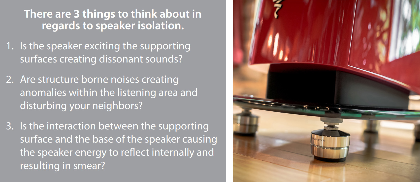
The first two points are commonly understood and are typically the first things that come to mind when
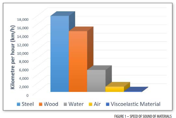
thinking of speaker isolation. When a speaker is resting on a surface like a flimsy desktop, it is easy to imagine the impact that the speaker can have on the surface. The speaker is vibrating and exciting the supporting surface which is creating dissonant sounds. The second point describes a situation where the energy resonates through the supporting surface and carries into other rooms or excites other objects within the listening area. In response to this, high-end pro studios isolate or “float” their control rooms in order to eliminate structure borne energy transfer into the room and also out of the room. The solid materials are in fact better conductors of sound compared to air which is illustrated in figure 1. For example, a train can be heard through the structure borne noise in the tracks well before the soundwaves can he heard.
Internal reflections are another consequence of speaker placement which can result in a loss of sound clarity and can cause sounds to become less three dimensional and spacious. Vibrations are inherent in the speaker, but any vibrations reflecting off the supporting surface and returning through any mechanical connection are a cause of internal reflections. Imagine, for example, bolting a pipe to a wall and hitting it with a hammer. The vibrations go down the pipe, hit the wall and then come back. These internal reflections cause smear which results in a loss of sound clarity and openness. Any artifacts (smear) that are replicated in the two channels are perceived to be in the middle, causing the sound stage to collapse.
TESTING AT NATIONAL RESEARCH COUNCIL OF CANADA (NRC)
Frequency Response Testing in the Anechoic Chamber
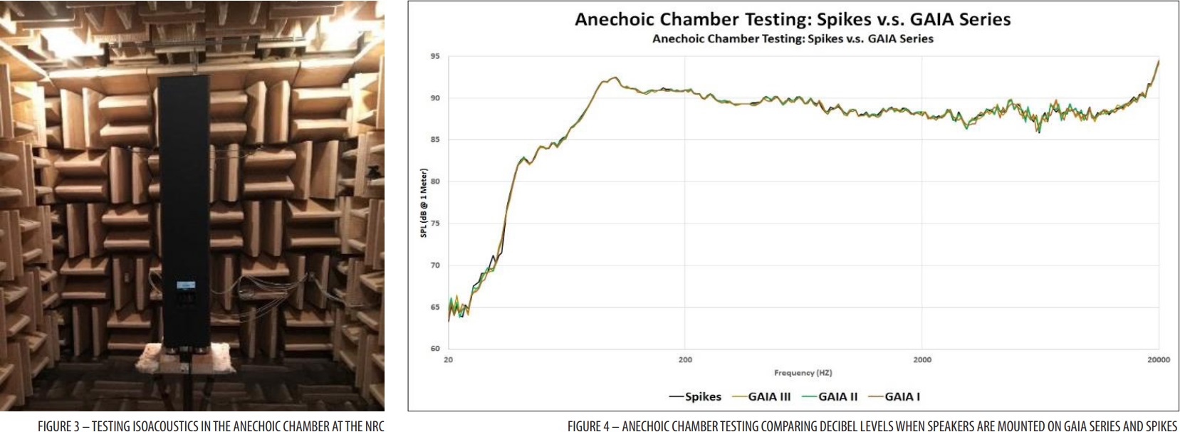
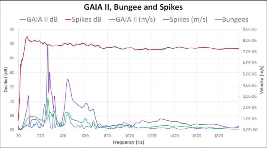
There is a common misconception that isolation can result in a loss in output in the lower frequencies. Testing completed in the Anechoic Chamber at the NRC measured the decibel level output at various frequencies when using IsoAcoustics products and using spikes. The results using both IsoAcoustics isolation and spikes are compared on fgure 4. The testing concludes that there was no colorization when using the GAIA isolators. The decibel output is consistent between spikes and the GAIA’s through the tested frequencies ranging from 20 Hz to 20 kHz. One of the IsoAcoustics fundamental principles is to ensure sound accuracy and no colorization.
 Laservibrometer: Laser Scanning Vibrometry
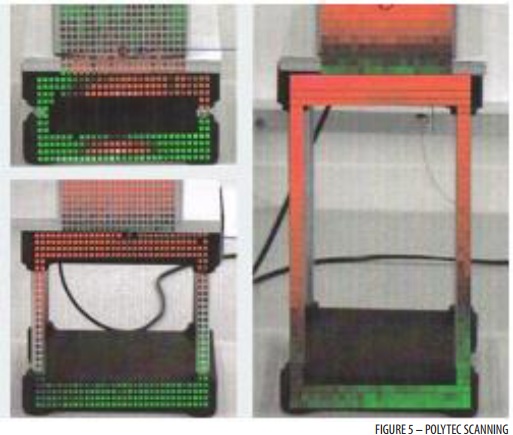
The Laservibrometer is an instrument that is used to make vibration measurements of a surface. Laser scanning vibrometry rapidly scans point-by-point over the test object’s surface to measure vibration levels at various points. The results of the laser scanning vibrometry are shown in figure 5 which helps to illustrate how IsoAcoustics manages the energy of the speaker and reduces the transfer of resonant energy from speaker to the supporting surface.
IsoAcoustics products are designed and tested to provide a high degree of speaker isolation to greatly reduce the symptoms associated with the transfer of resonant energy from the speaker to the supporting surfaces.
Measuring Vibrations: IsoAcoustics vs Spikes
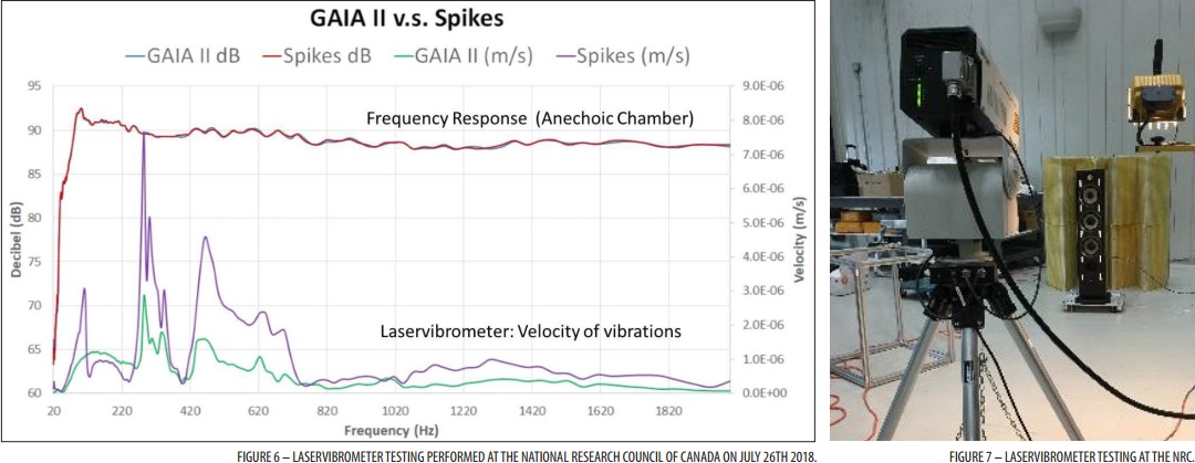
Figure 6 compares the velocity of the vibrations on spikes and on GAIA isolators. This example shows results through frequencies from 20 Hz to 2 kHz. The velocity represents the speed of the vibrations measured in meters per second.
Figure 6 is a photo of the setup used at the NRC to test the GAIA’s and spikes with the laservibrometer.
Summary:
- The velocity of the speaker vibrations are measured in m/s which is located on the secondary Y-axis on the right side of the graph.
- The purple line represents the velocity of the vibrations of the speaker with the speakers mounted on spikes.
- The green line represents the velocity of the vibrations with the speakers mounted on the IsoAcoustics isolation feet.
- Results of the frequency response testing in the Anechoic Chamber are charted on the same graph. The decibel levels are shown on the Y-axis located on the left side of the graph.
The graph shows that the velocity of the vibrations were signifcantly lower when the GAIA isolators were installed on the speakers. The change in the levels of the vibrations was also smoother as the output of the speaker traveled through the range of frequencies. The reduction of vibration is related to the boundary condition which is explained next.
Closed Boundary Conditions vs Boundary Conditions with Absorption
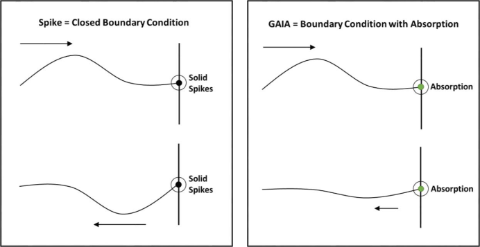
The reduction in vibrations can be explained by the way that IsoAcoustics isolation manages the energy of the speaker to reduce internal reflections. The vibrations when spikes are used is greater in comparison because the vibrations are hitting the solid surface and conducted back to create internal reflections. This is referred to as a closed boundary condition and is illustrated in figure 8. To help visualize this, imagine throwing a large rock into a swimming pool. The ripples hit the hard edges and converge again as we are about to throw the next rock. In this example, we can eliminate the internal reflections by making the pool infinitely large. The IsoAcoustics isolation technology is reducing the internal reflections similar to eliminating the reflections in a swimming pool by removing the edges. The IsoAcoustics isolation technology provides a boundary condition with absorption to greatly reduce the reflections. The effects of the boundary condition with absorption using IsoAcoustics are illustrated in Figure 9.
Measuring Vibrations: Speakers suspended on bungee cords to provide baseline
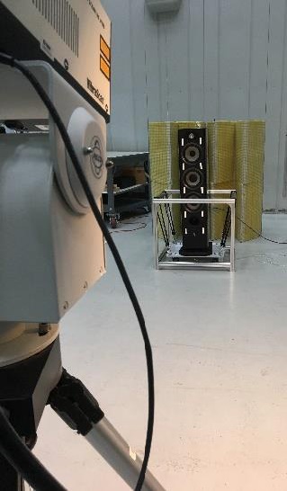
In order to test how much vibration is inherant in the speaker and how much is related to the boundary condition, the testing was repeated with the speakers suspended on bungee cords to remove the connection to the supporting surface.
The speakers were tested on the GAIA’s and then the test was repeated with the speakers raised onto spikes using solenoids. The test was repeated again with the speaker base suspended by bungee cords. The variation in height was kept to within ¼” (less than ½ a wave length at 20 khz) when changing between spikes, GAIA’s or Bungee. This setup allowed for the testing of each setup while keeping other variables consistent.
Figure 10 compares the velocity of the vibrations on spikes, on GAIA isolators and also with the speakers suspended on bungee cords. The blue line represents the level of vibration that was recorded when the speaker was suspended on bungee cords. The results show that isolation with bungee cords reduced vibrations at a similar level as with the speaker isolated with IsoAcoustics GAIA isolators. The cabinet vibrations of the speakers isolated with GAIA and with Bungee cords resulted in a reduction in cabinet vibrations through the introduction of an absorption layer that reduced secondary reflections.
The bungee cords were very effective at managing the vibrations, but the sound lacked definition and was less sharp. The IsoAcoustics patented design manages the energy on axis to provide improved sound clarity. The IsoAcoustics patented isolation design is explored next.
ISOACOUSTICS PATENTED ISOLATION DESIGN
The IsoAcoustics award winning patented isolation design manages the energy of the speaker to provide the best speaker performance. The effectiveness of the isolation is a result of the shape, thickness, durometer and characteristics of their proprietary isolation material and the way the top and bottom isolators function together with the internal insert to manage vibrations.
Managing energy on-axis
IsoAcoustics stands are directional and designed to be positioned with the logo facing in the same direction as the motive forces of the speakers. As a result they manage the energy on-axis as opposed to homogenous materials that allow the speakers to oscillate in all directions. This method of managing the energy provides a high degree of isolation, improved sound clarity, focus and openness.
Connection to speaker and supporting surface
IsoAcoustics products are designed to connect to the base of the speaker and to the supporting surface so that the energy is effectively managed by the internal isolators. The shape of the isolators creates a suction cup effect on smooth surfaces or provides a strong friction grip if the surface is textured.
IsoAcoustics offers a variety of models, each tuned for different weight ranges. The weight limits specified by IsoAcoustics are based on the performance curve. The performance of the isolation is declining as the weight approaches the specified weight limits and performance decreases more the further the weight limit is exceeded.

